IPC · Section B & C · Free response

Electricity and Magnetism

13 questions — reveal each answer and worked solution.

2010-12B · Writtend2Electricity and Magnetism · Filament resistance and temperature

(2010-12) An electric light bulb is connected to a suitable power supply.

The current flowing through the bulb quickly rises to a maximum when the power supply is first connected but then falls to settle at a lower constant value after a short time.
Explain why the constant current flowing in the bulb is less than the maximum value.

Show worked solution
Explanation

When the power supply is first connected, the filament of the bulb is cold. A metal filament has a relatively low resistance when its temperature is low, so the initial resistance of the filament is small. For a fixed supply voltage $V$, the current is given by $$ I=\frac{V}{R} $$ so a small initial resistance $R$ produces a large initial current, which is why the current quickly rises to a maximum just after switching on.

As the large current flows, electrical energy is dissipated in the filament at a rate (power) $$ P=I^2R $$ This heating rapidly raises the filament temperature. In a metal, increasing temperature causes increased lattice vibrations, which increases the rate at which conduction electrons collide with the lattice. This reduces electron mobility and increases the filament’s resistivity, so the resistance of the filament increases as it heats up (positive temperature coefficient).

Because the supply voltage $V$ is (approximately) constant, the increase in filament resistance causes the current to decrease according to $I=V/R$. The filament reaches a steady operating temperature when the electrical power input equals the rate of heat loss (by radiation and conduction/convection). At that steady temperature the resistance is larger than when cold, so the steady (constant) current is smaller than the initial maximum current.

2012-14C · Writtend3Electricity and Magnetism · Kepler's third law and orbital motion

(2012-14) Relative motion of Mars.

Data: Distance of Earth from the Sun:
149 million kilometres $\left(1.49 \times 10^{11} \mathrm{~m}\right)$
Distance of Mars from the Sun: 228 million kilometres $\left(2.28 \times 10^{11} \mathrm{~m}\right)$
Length of one Earth Year:
365 earth days

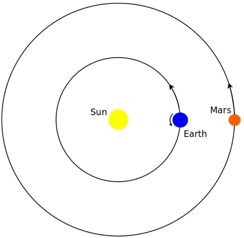
The diagram, which is most certainly not to scale, shows the orbits of the Earth and Mars about the Sun.

figure

(a) Using the data given above, and assuming the orbit is circular, show that the orbital speed of the Earth about the Sun is approximately $29,700 \mathrm{~m} / \mathrm{s}$.
In 1619 Johannes Kepler published his third law of planetary motion which stated that the square of the period of the orbit (time to go round the sun) was proportional to the cube of the radius of the orbit around the sun.
$\mathrm{T}^{2} \propto \mathrm{R}^{3}$
or $\quad T^{2}=k R^{3}$

$$ \begin{aligned} & \mathrm{T}=\text { time for one orbit } \\ & \mathrm{R}=\text { radius of orbit } \\ & \mathrm{k}=\text { constant } \end{aligned} $$

(b) Using the data for Earth, calculate the value of the constant, k , and state the appropriate units.
(c) Hence, calculate the orbital period and the orbital speed of Mars.
(d) Consider the situation shown in the diagram above, when the sun, Earth and Mars are in line and Earth and Mars are on the same side of the sun. As seen from Earth, Mars will appear to move over the next few nights, relative to the background stars. State and explain which direction (East to West or West to East) Mars will appear to move.

Show worked solution
(a)

For an object moving in a circular orbit of radius $R$ with orbital period $T$, the orbital speed is the circumference divided by the time for one orbit: $$ v=\frac{2\pi R}{T} $$ Convert one Earth year to seconds: $$ T=365\times 24\times 3600=3.1536\times 10^{7}\ \mathrm{s} $$ Now substitute $R=1.49\times 10^{11}\ \mathrm{m}$ and $T=3.1536\times 10^{7}\ \mathrm{s}$: $$ v=\frac{2\pi(1.49\times 10^{11})}{3.1536\times 10^{7}} \approx 2.97\times 10^{4}\ \mathrm{m\,s^{-1}} \approx 29{,}700\ \mathrm{m\,s^{-1}} $$ This matches the required approximate value of $29{,}700\ \mathrm{m\,s^{-1}}$ for Earth's orbital speed.

(b)

Kepler's third law is $T^{2}=kR^{3}$, so the constant is $$ k=\frac{T^{2}}{R^{3}} $$ Using Earth's values $T=3.1536\times 10^{7}\ \mathrm{s}$ and $R=1.49\times 10^{11}\ \mathrm{m}$: $$ k=\frac{(3.1536\times 10^{7})^{2}}{(1.49\times 10^{11})^{3}} \approx 3.0\times 10^{-19}\ \mathrm{s^{2}\,m^{-3}} $$ The units follow from $k=T^{2}/R^{3}$, giving $\mathrm{s^{2}\,m^{-3}}$.

(c)

For Mars, $R=2.28\times 10^{11}\ \mathrm{m}$. From $T^{2}=kR^{3}$, the orbital period is $$ T=\sqrt{kR^{3}}=\sqrt{(3.0\times 10^{-19})(2.28\times 10^{11})^{3}}\approx 5.97\times 10^{7}\ \mathrm{s} $$ In Earth days this is $T/(86400)\approx 691\ \mathrm{days}$, which is about $1.89$ Earth years. The orbital speed again comes from $v=2\pi R/T$: $$ v=\frac{2\pi(2.28\times 10^{11})}{5.97\times 10^{7}}\approx 2.4\times 10^{4}\ \mathrm{m\,s^{-1}} $$ So Mars has orbital period $\approx 5.97\times 10^{7}\ \mathrm{s}$ ($\approx 691$ days) and orbital speed $\approx 2.4\times 10^{4}\ \mathrm{m\,s^{-1}}$.

(d)

Mars will appear to move from East to West relative to the background stars (retrograde motion). Earth is closer to the Sun, so it has a smaller orbit and a shorter period, meaning its orbital speed and angular speed about the Sun are greater than Mars's. When Earth and Mars are in line on the same side of the Sun (Sun--Earth--Mars), Earth overtakes Mars, so the line of sight from Earth to Mars sweeps backward against the distant (effectively fixed) background stars, producing an apparent East-to-West drift over successive nights.

2013-11B · Writtend2Electricity and Magnetism · Stopping distance and speed dependence

(2013-11) Explain what effect doubling the speed of a vehicle will have on the total stopping distance if all other factors such as driver alertness, braking performance and road surface stay the same.

Show worked solution
Stopping distance idea The total stopping distance is the sum of the distance traveled during the driver’s reaction time (thinking distance) and the distance traveled while the brakes slow the vehicle to rest (braking distance), so $$d_{\rm stop}=d_{\rm think}+d_{\rm brake}$$ Effect on thinking distance If driver alertness stays the same, the reaction time $t_r$ is constant, and the thinking distance is $d_{\rm think}=vt_r$, so doubling speed from $v$ to $2v$ makes $$d_{\rm think}\rightarrow 2d_{\rm think}$$ Effect on braking distance If braking performance and road surface stay the same, the maximum deceleration magnitude $a$ is (approximately) constant, and using constant-acceleration kinematics from speed $v$ to $0$ gives $$0=v^2-2ad_{\rm brake}\quad\Rightarrow\quad d_{\rm brake}=\frac{v^2}{2a}$$ so doubling speed from $v$ to $2v$ makes $$d_{\rm brake}\rightarrow \frac{(2v)^2}{2a}=4\frac{v^2}{2a}=4d_{\rm brake}$$ Overall effect on total stopping distance Combining both changes, doubling the speed doubles the thinking distance but quadruples the braking distance, so the new total stopping distance is $$d_{\rm stop,new}=2d_{\rm think}+4d_{\rm brake}$$ which means the total stopping distance increases by more than a factor of $2$ and is dominated by the braking part at higher speeds because it grows with $v^2$.
2014-14C · Writtend4Electricity and Magnetism · Total internal reflection and modal dispersion in optical fibres

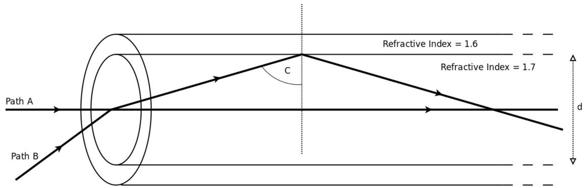
(2014-14: This question is about the maximum frequency at which digital data can be transmitted along a fibre optic cable.) A fibre optic cable is made from two layers of glass as shown in the diagram below.

The inner 'core' of the fibre has a higher refractive index than the outer layer. An optical signal can travel directly along the fibre taking path A in the diagram. Alternatively, the signal can bounce along the inside of the fibre therefore taking a longer path.
The maximum distance travelled occurs when the angle is just greater than the critical angle, taking path $B$ in the diagram.

figure

Theory: $\quad$ Refractive index ( n ) = speed of light in a vacuum / speed of light in medium For a light ray crossing a boundary with an angle of incidence $\theta_{1}$ and an angle of refraction $\theta_{2}$ and travelling from medium 1 (having a refractive index of $n_{1}$ ) to medium 2 (with refractive index $n_{2}$ ),

Snell's Law of refraction gives:

$$ \sin \left(\theta_{1}\right) / \sin \left(\theta_{2}\right)=n_{2} / n_{1} $$

The critical angle is when the angle of incidence $\left(\theta_{1}=C\right)$ is such that the angle of refraction is $\theta_{2}=90^{\circ}$
(a) Show that the critical angle (C) as shown in the diagram is about $70^{\circ}$
(b) For a fibre optic cable 1 km long, show that the time difference between a signal taking path $A$ and a signal taking path $B$ is approximately $0.4 \mu \mathrm{~s}$
Core diameter, $\mathrm{d}=0.6 \mathrm{~mm}$
Speed of light in a vacuum $=3 \times 10^{8} \mathrm{~m} / \mathrm{s}$
Hint: Sketch the two paths with $B$ crossing the fibre and use geometry to calculate how much longer path $B$ is than path $A$. Knowing the difference in the lengths of the paths, calculate the time difference.
The digital signal emerging from the end of the fibre is a combination of the signals that have travelled along the two different paths.
When the 'ON' from path A arrives at the same time as an 'OFF' from path $B$, the signal is lost.
(c) Hence calculate the maximum frequency that can be transmitted along the cable
(d) State and explain how each of the following changes affects the maximum frequency that can be transmitted:
(i) Decreasing the diameter (d) of the core
(ii) Decreasing the refractive index of the outer layer
[0pt] [2 marks]

Show worked solution
(a)

The critical angle $C$ at the core--outer boundary satisfies $\sin C=n_{\text{outer}}/n_{\text{core}}$. Using $n_{\text{core}}=1.60$ and $n_{\text{outer}}=1.50$, $$ \sin C=\frac{1.50}{1.60}=0.9375\quad\Rightarrow\quad C=\sin^{-1}(0.9375)=69.7^\circ\approx 70^\circ $$

(b)

For the axial ray (path A), the distance is simply the fiber length $L=1.0\times10^3\,\mathrm{m}$. The speed of light in the core is $v=c/n_{\text{core}}=(3.0\times10^8)/1.60=1.875\times10^8\,\mathrm{m\,s^{-1}}$. The travel time for path A is $$ t_A=\frac{L}{v}=\frac{1.0\times10^3}{1.875\times10^8}=5.33\times10^{-6}\,\mathrm{s}=5.33\,\mu\mathrm{s} $$ For path B (maximum angle ray), the ray travels at angle $\theta$ to the axis where the incidence at the wall equals the critical angle: $90^\circ-\theta=C$, so $\theta=90^\circ-C\approx 20^\circ$. This ray travels a longer geometric path by factor $1/\cos\theta\approx 1.064$, so $$ t_B=\frac{L}{v\cos\theta}\approx(5.33\times10^{-6})(1.064)=5.67\times10^{-6}\,\mathrm{s}=5.67\,\mu\mathrm{s} $$ The time difference is $$ \Delta t=t_B-t_A\approx 5.67-5.33=0.34\times10^{-6}\,\mathrm{s}\approx 0.4\,\mu\mathrm{s} $$

(c)

The maximum frequency is limited by pulse spreading: if bits are shorter than the time spread, they overlap. A simple criterion is $f_{\max}\approx 1/(2\Delta t)$: $$ f_{\max}\approx\frac{1}{2(0.4\times10^{-6})}\approx 1.25\times10^6\,\mathrm{Hz}\approx 1.3\,\mathrm{MHz} $$

(d)

Decreasing the core diameter reduces the number of possible ray paths (modes), which reduces modal dispersion and therefore increases $f_{\max}$. Decreasing the refractive index of the outer layer reduces the critical angle (since $\sin C=n_{\text{outer}}/n_{\text{core}}$), allowing more oblique rays and increasing modal dispersion, which decreases $f_{\max}$.

2016-11B · Writtend2Electricity and Magnetism · Friction in locomotion

(2016-11) It is easy to walk along on a dry flat surface such as a pavement. However, it is very difficult to walk along on ice due to the fact that the friction forces are very much reduced on ice.

Explain why friction is necessary for us to walk along on a surface.

Show worked solution
Solution Walking requires you to push backward on the ground with your foot so that the ground can push you forward; the forward push from the ground is a static friction force, and without enough static friction you cannot accelerate your body forward without slipping. The maximum available static friction is set by the normal contact force $N$ and the coefficient of static friction $\mu_s$: $$ f_{s,\max}=\mu_s N $$ On a dry pavement, $\mu_s$ is relatively large, so $f_{s,\max}$ is large enough that your shoe can grip the surface; when you push backward on the ground, the static friction force can match what is needed to move you forward, and your foot does not slide. On ice, $\mu_s$ is much smaller because a very thin meltwater layer and the smooth surface reduce the microscopic interlocking between shoe and ground, so $f_{s,\max}$ becomes small; when you try to push backward with your foot, the required friction to prevent slipping often exceeds $f_{s,\max}$, static friction cannot supply it, and your foot transitions to slipping with even smaller kinetic friction $f_k=\mu_k N$, making it difficult to generate the forward driving force needed for walking.
2017-14C · Writtend4Electricity and Magnetism · Battery energy storage and supercapacitor comparison

(2017-14: This question is about energy in a chemical cell and whether or not other technology could easily replace the chemical cell.) The most common chemical cell is probably the 'AA battery' used in many everyday appliances.
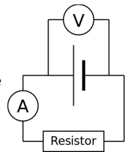
Such an AA chemical cell was connected to a resistor in a circuit as shown.
The voltage across the cell and the current in the circuit were measured at intervals throughout the day until the cell was completely flat.
The results are shown in the table.

figure
\begin{tabular}{c} Elapsed Time
/ Hours

& Voltage / V & Current / mA
\hline 0 & 1.6 & 200
\hline 1 & 1.6 & 200
\hline 3 & 1.4 & 175
\hline 6 & 1.2 & 150
\hline 7 & 1.1 & 140
\hline 8 & 0.2 & 25
\hline \endtabular

(a) Show that the power delivered by the cell when timing started was about 0.3 W
(b) Show that the energy delivered by the cell in the first hour of the experiment was approximately 1150 J
(c) Use the data in the table to estimate the total energy delivered by the cell over the course of the whole experiment

Rather than giving the actual energy deliverable by a cell in joules, the "energy content" or capacity of the cell is often quoted by the manufacturer in units of milliamp hours (mAh).
For this particular cell, the manufacturer quotes a capacity of 1500 mAh .
This means that, in theory, the cell should deliver 1500 mA for one hour.
(d) Determine whether or not the manufacturer's claims are consistent with the recorded data
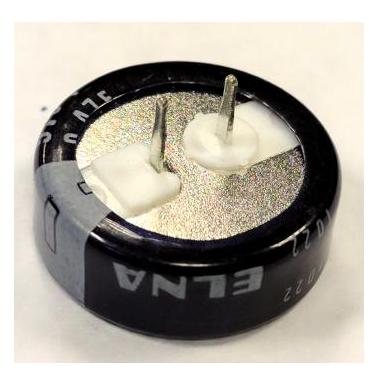
An alternative technology uses a component called a supercapacitor to store charge.
The capacitance (C) of the supercapacitors is measured in farads (F).
For a supercapacitor, the energy stored is given by $E=\frac{1}{2} C V^{2}$

figure

where V is the voltage across the capacitor when it is charged.
(e) Consider a supercapacitor with a capacitance of 15 F that is charged so that it has a voltage of 2.8 V across the terminals.
Show that the energy stored in this case is approximately 60 J

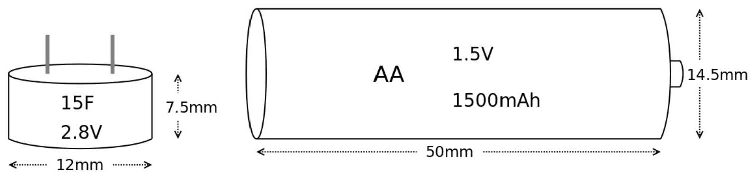
The dimensions of a AA cell and a supercapacitor are shown in the diagram.

NOT TO SCALE

figure

Energy density can be defined as the energy stored per $\mathbf{c m}^{\mathbf{3}}$ for the cell or supercapacitor.
(f) Calculate the energy density for the AA chemical cell and for the supercapacitor and comment on the feasibility of replacing the traditional AA battery with an equivalent device made from supercapacitors
Energy density of AA cell = $\mathrm{Jcm}^{-3}$

One of the great advantages of supercapacitors is that they can discharge very quickly and hence deliver very large currents.

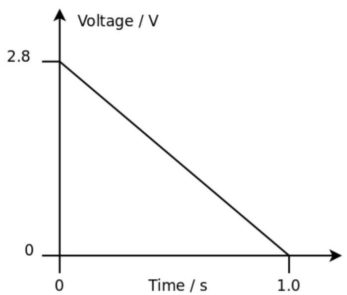
A 15F supercapacitor, initially charged to 2.8 V , is discharged in 1 second.

The discharge circuit is arranged to ensure the discharge current remains constant throughout the 1 second period.

figure

As the supercapacitor discharges, the voltage reduces steadily from 2.8 V to 0 V as shown on the voltage - time graph.
(g) Calculate the discharge current

Show worked solution
(a)

The electrical power delivered by a source is $P=VI$. At the start, $V=1.6\ \mathrm{V}$ and $I=200\ \mathrm{mA}=0.200\ \mathrm{A}$, so $$ P=(1.6)(0.200)=0.32\ \mathrm{W}\approx 0.3\ \mathrm{W} $$

(b)

Energy transferred in time $t$ at (approximately) constant power is $E=Pt$. During the first hour, the readings at $0$ and $1$ hour are the same, so take $P=0.32\ \mathrm{W}$ for $t=1\ \mathrm{h}=3600\ \mathrm{s}$. $$ E=(0.32)(3600)=1152\ \mathrm{J}\approx 1150\ \mathrm{J} $$

(c)

The total energy is the area under the power--time graph, and power changes with time, so estimate using trapezia over each time interval. First calculate power at each recorded time using $P=VI$ (with current in amperes): At $0\ \mathrm{h}$: $P_0=(1.6)(0.200)=0.32\ \mathrm{W}$ At $1\ \mathrm{h}$: $P_1=(1.6)(0.200)=0.32\ \mathrm{W}$ At $3\ \mathrm{h}$: $P_3=(1.4)(0.175)=0.245\ \mathrm{W}$ At $6\ \mathrm{h}$: $P_6=(1.2)(0.150)=0.180\ \mathrm{W}$ At $7\ \mathrm{h}$: $P_7=(1.1)(0.140)=0.154\ \mathrm{W}$ At $8\ \mathrm{h}$: $P_8=(0.2)(0.025)=0.005\ \mathrm{W}$

Trapezium estimate on each interval: $E\approx \dfrac{(P_a+P_b)}{2}\Delta t$, with $\Delta t$ in seconds. $$ E_{0\to 1}=\frac{0.32+0.32}{2}(3600)=1152\ \mathrm{J} $$ $$ E_{1\to 3}=\frac{0.32+0.245}{2}(2\times 3600)=2034\ \mathrm{J} $$ $$ E_{3\to 6}=\frac{0.245+0.180}{2}(3\times 3600)=2295\ \mathrm{J} $$ $$ E_{6\to 7}=\frac{0.180+0.154}{2}(3600)=601\ \mathrm{J} $$ $$ E_{7\to 8}=\frac{0.154+0.005}{2}(3600)=286\ \mathrm{J} $$ $$ E_{\text{total}}\approx 1152+2034+2295+601+286=6368\ \mathrm{J}\approx 6.4\times 10^{3}\ \mathrm{J} $$

(d)

Capacity in $\mathrm{mAh}$ is the area under the current--time graph (current in mA, time in h): $$ Q\approx \sum \frac{(I_a+I_b)}{2}\Delta t $$ Using trapezia (with $\Delta t$ in hours): $0\to 1$: $\dfrac{200+200}{2}(1)=200\ \mathrm{mAh}$ $1\to 3$: $\dfrac{200+175}{2}(2)=375\ \mathrm{mAh}$ $3\to 6$: $\dfrac{175+150}{2}(3)=487.5\ \mathrm{mAh}$ $6\to 7$: $\dfrac{150+140}{2}(1)=145\ \mathrm{mAh}$ $7\to 8$: $\dfrac{140+25}{2}(1)=82.5\ \mathrm{mAh}$ $$ Q_{\text{delivered}}\approx 200+375+487.5+145+82.5=1290\ \mathrm{mAh} $$ The manufacturer claims $1500\ \mathrm{mAh}$, but the data show about $1290\ \mathrm{mAh}$ delivered in this test, which is lower by about $1500-1290=210\ \mathrm{mAh}$ (about $14\%$). This is not fully consistent, although it is of the same order; in practice, quoted capacities often depend on discharge current, cutoff voltage, temperature, and test conditions, so a lower measured value here is plausible.

(e)

For a capacitor, stored energy is $E=\dfrac{1}{2}CV^2$. With $C=15\ \mathrm{F}$ and $V=2.8\ \mathrm{V}$, $$ E=\frac{1}{2}(15)(2.8)^2=7.5\times 7.84=58.8\ \mathrm{J}\approx 60\ \mathrm{J} $$

(f)

Energy density is energy per unit volume. Model each device as a cylinder of volume $V_{\text{cyl}}=\pi r^2 h$ and use the dimensions shown (AA cell: diameter $1.4\ \mathrm{cm}$, length $5.0\ \mathrm{cm}$; supercapacitor: diameter $2.0\ \mathrm{cm}$, length $3.0\ \mathrm{cm}$).

AA cell volume: $r=0.7\ \mathrm{cm}$, $h=5.0\ \mathrm{cm}$ $$ V_{\mathrm{AA}}=\pi(0.7)^2(5.0)=7.70\ \mathrm{cm^3} $$ Using the total delivered energy from part (c), $E_{\mathrm{AA}}\approx 6.37\times 10^3\ \mathrm{J}$, $$ u_{\mathrm{AA}}=\frac{E_{\mathrm{AA}}}{V_{\mathrm{AA}}}=\frac{6.37\times 10^3}{7.70}\approx 8.3\times 10^2\ \mathrm{J\,cm^{-3}} $$

Supercapacitor volume: $r=1.0\ \mathrm{cm}$, $h=3.0\ \mathrm{cm}$ $$ V_{\mathrm{SC}}=\pi(1.0)^2(3.0)=9.42\ \mathrm{cm^3} $$ Using $E_{\mathrm{SC}}\approx 60\ \mathrm{J}$ from part (e), $$ u_{\mathrm{SC}}=\frac{60}{9.42}\approx 6.4\ \mathrm{J\,cm^{-3}} $$

Comparison and feasibility: the AA cell energy density is roughly $\dfrac{8.3\times 10^2}{6.4}\approx 1.3\times 10^2$ times larger, so an equivalent supercapacitor-based device (same stored energy) would need of order $10^2$ times the volume, which is generally not feasible as a direct replacement for an AA battery when energy storage is the main requirement.

(g)

For a capacitor, the charge change is $\Delta Q=C\Delta V$, and constant current means $I=\dfrac{\Delta Q}{\Delta t}$. Here $C=15\ \mathrm{F}$, $\Delta V=2.8\ \mathrm{V}$ (from $2.8\ \mathrm{V}$ to $0$), and $\Delta t=1\ \mathrm{s}$. $$ \Delta Q=C\Delta V=(15)(2.8)=42\ \mathrm{C} $$ $$ I=\frac{\Delta Q}{\Delta t}=\frac{42}{1}=42\ \mathrm{A} $$

2018-11B · Writtend2Electricity and Magnetism · Thermal conductivity and sensation of cold

(2018-11) On a cold winter's day a piece of wood and a piece of metal are left outside for a long time. When the wood and then the metal are each handled in turn the metal feels much colder that the wood.

Explain why the metal feels much colder than the wood even though they have both been outside and are therefore at the same temperature.

Show worked solution
Key idea: same temperature, different heat transfer rate

Both the wood and the metal have been outside for a long time, so they have reached thermal equilibrium with the outdoor air and therefore are at (approximately) the same temperature. The reason they feel different is not that one is at a lower temperature than the other, but that they remove thermal energy from your hand at very different rates, and your skin's temperature sensors largely respond to the rate of heat loss from your skin.

Heat flow from your hand

Your hand is much warmer than either object, so when you touch the surface, heat flows from your skin into the material. The rate of conduction near the contact can be related to Fourier's law, in the simplified form $$ \frac{Q}{t}\propto k\,A\,\frac{\Delta T}{L} $$ where $k$ is the thermal conductivity of the material, $A$ is the contact area, $\Delta T$ is the temperature difference between your skin and the object, and $L$ represents the distance over which the temperature changes inside the material.

For wood, $k$ is small, so the heat flow rate is small: the surface of the wood in contact with your skin warms up quickly and then acts as an insulating layer, reducing further heat loss from your hand. For metal, $k$ is large, so heat is conducted away rapidly from the contact region into the bulk metal; the surface you touch is continually "replaced" (thermally) by colder metal from deeper inside, keeping the surface temperature near the outdoor temperature and maintaining a large heat flow from your hand.

Thermal effusivity: why metal keeps drawing heat

A more complete way to express "how cold something feels" on touch is thermal effusivity $e$, which measures how effectively a material can draw heat from another body during contact: $$ e=\sqrt{k\,\rho\,c} $$ where $\rho$ is density and $c$ is specific heat capacity. Metals generally have much larger $k$ (and often substantial $\rho$), giving them a much larger $e$ than wood. A larger $e$ means the material can absorb heat from your skin more rapidly without its surface temperature rising much, so your skin cools faster and you perceive it as colder.

Conclusion

The metal feels much colder than the wood even though both are at the same outdoor temperature, because metal has far higher thermal conductivity (and typically higher thermal effusivity), so it removes heat from your hand much faster; wood is a poor conductor, so it warms at the surface and slows the heat loss from your skin, feeling less cold.

2019-12B · Writtend2Electricity and Magnetism · Apparent weight and Newton's second law

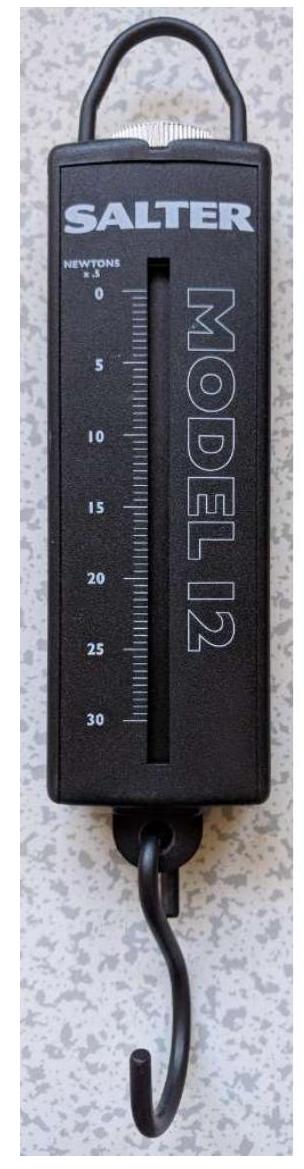
(2019-12) A student is investigating how a 30 N spring balance works. A 1 kg mass is suspended from the spring balance. The student stands on a table and holds the spring balance stationary.

Whilst holding the spring balance, the student jumps off the table and lands on the floor. A colleague videos the reading on the spring balance throughout the experiment.

An analysis of the video shows that:
When the student is standing on the table and the balance is stationary (and not accelerating), the reading is 10 N
$\square$ When the student is falling from the table to the floor, the reading is 0 N
$\square$ When the student lands, the reading is momentarily greater than 10 N

Explain these observations

figure
Show worked solution
(a)

A spring balance measures the tension $T$ in the spring (the force the spring exerts on the mass). When the student is standing still on the table, the mass is also stationary, so its acceleration is $a=0$. Applying Newton's second law to the $1\,\mathrm{kg}$ mass (upward positive): $T - mg = ma = 0$, so $T=mg$. With $m=1\,\mathrm{kg}$ and $g\approx 10\,\mathrm{N\,kg^{-1}}$, $T\approx 10\,\mathrm{N}$, matching the observed reading of $10\,\mathrm{N}$.

(b)

When the student jumps off the table, the balance and the mass are in free fall. The key idea is that "falling" does not mean there is no gravity; it means the whole system accelerates downward at approximately $a=g$. For the mass, Newton's second law gives $T - mg = ma = -mg$, which rearranges to $T=0$. Physically, the mass and the balance are accelerating downward together, so the spring does not need to stretch to support the mass; the mass is effectively “weightless” relative to the balance, giving a reading of $0\,\mathrm{N}$.

(c)

When the student lands, the student's hand (and the balance) rapidly decreases its downward speed to zero over a short time, meaning the balance experiences a large upward acceleration. The mass must be accelerated upward as well, so the spring must provide an additional upward force beyond the weight. With upward positive and an upward acceleration $a>0$ during the stopping phase, $T - mg = ma$, so $T = mg + ma$, which is greater than $mg$. Therefore the spring balance reading becomes momentarily greater than $10\,\mathrm{N}$ while the student is decelerating on landing, then returns to $10\,\mathrm{N}$ once everything is stationary again.

2020-11B · Writtend2Electricity and Magnetism · Gas laws and absolute zero

(2020-11) When gases are heated they can expand.

This phenomenon is used in a simple thermometer called a gas thermometer. A glass bulb contains gas which is trapped by a small bead of mercury in a capillary tube. When the temperature of the gas increases it expands and the mercury moves up the capillary tube. The top of the capillary tube is open.

Explain why the gas expands when it is heated.

Show worked solution
When a gas is heated, its molecules gain kinetic energy, so their average speed increases. This makes the molecules collide with the walls of the container more frequently and with greater change of momentum each time they collide, so the force on the walls increases and therefore the pressure tends to rise.

In a gas thermometer the top of the capillary tube is open, so the gas is effectively kept at (approximately) constant external pressure, equal to atmospheric pressure (the mercury bead acts like a movable plug that transmits the external pressure to the gas). Since the pressure is approximately constant, the gas cannot simply increase its pressure when heated; instead it increases its volume until its pressure matches the external pressure again.

This is described by the ideal gas relationship $pV \propto T$ for a fixed amount of gas. With $p$ approximately constant, the volume must be proportional to the absolute temperature:

$$ pV=nRT \;\;\Rightarrow\;\; V=\frac{nR}{p}T $$

So when $T$ increases, $V$ increases: the gas expands. The expanding gas pushes the mercury bead along the capillary tube, increasing the gas volume and moving the bead upward, which provides a temperature reading.

2022-13C · Writtend3Electricity and Magnetism · Kinematics on inclined ramp and error analysis

(2022-13) This question is about a familiar school practical to measure acceleration where a student investigates the acceleration of a toy car on a ramp.

The height of the ramp is changed and the resulting acceleration obtained from the measurements given below.

The experimental setup is shown in the diagram.

figure

To measure the acceleration, the student releases the car from rest at the top of the ramp and uses a stopwatch to time how long it takes for the car to reach the bottom of the ramp. The student records the following results:

Ramp height $/ \mathrm{cm}$time (1 $1^{\text {st }}$ attempt) $/ \mathrm{s}$time $\left(2^{\text {nd }}\right.$ attempt) $/ \mathrm{s}$time $\left(3^{\text {rd }}\right.$ attempt) $/ \mathrm{s}$
52.452.482.41

a) Calculate the average speed of the toy car.
The student's teacher states "the final speed of the car is twice the average speed"
b) Explain why the teacher's statement is reasonable, stating any assumptions that are necessary.
c) Calculate the acceleration of the toy car.
The teacher states "theory suggests that the acceleration of the car is directly proportional to the height of the ramp"

The student takes further readings of time for different heights of the ramp

Ramp height $/ \mathrm{cm}$time (1 $1^{\text {st }}$ attempt) $/ \mathrm{s}$time $\left(2^{\text {nd }}\right.$ attempt) $/ \mathrm{s}$time $\left(3^{\text {rd }}\right.$ attempt) $/ \mathrm{s}$
91.841.821.82
131.501.521.56

d) Use the student's data to show that acceleration of the car is proportional to the height of the ramp.
Theory shows that the relationship between ramp height ( $h$ ) and acceleration ( $a$ ) is given by the equation $a=\frac{g \times h}{L}$ where $g$ is the acceleration due to gravity and $L$ is the length of the ramp.
e) Use the student's data to calculate a value for the acceleration due to gravity.
The student comments that "the value of $g$ is not very accurate because we only measured the ramp height to the nearest $0.5 \mathbf{c m}$ ", but the student's teacher disagrees and replies, "the lack of accuracy is due to the random errors in the timing"
f) By considering the range of values of the timing and the uncertainty in the measurement of the height of the ramp, determine whether the conclusions stated by the student and by the teacher are justified.

Hint: Calculating the uncertainty in a measurement as a percentage of the average value makes it easier to appreciate the significance of the uncertainty.

Show worked solution
(a)

The car travels the length of the ramp, $L=1.20\,\mathrm{m}$ (from the diagram). The mean time for $h=5\,\mathrm{cm}$ is $$ \bar t=\frac{2.45+2.48+2.41}{3}=2.45\,\mathrm{s} $$ Average speed is distance divided by time, so $$ v_{\rm avg}=\frac{L}{\bar t}=\frac{1.20}{2.45}=4.91\times 10^{-1}\,\mathrm{m\,s^{-1}}\approx 0.49\,\mathrm{m\,s^{-1}} $$

(b)

If the car starts from rest ($u=0$) and accelerates uniformly down the ramp, then the speed increases linearly from $0$ to the final speed $v$. For uniform acceleration, the average speed over the journey is $$ v_{\rm avg}=\frac{u+v}{2} $$ With $u=0$, this gives $v_{\rm avg}=v/2$, so $v=2v_{\rm avg}$. This is reasonable provided the acceleration is approximately constant (small frictional variations, same release point, ramp is straight, and the car does not receive an extra push at release).

(c)

Using the result from part (b), the final speed is $$ v=2v_{\rm avg}=2(0.49)=0.98\,\mathrm{m\,s^{-1}} $$ With uniform acceleration from rest, $v=a t$, so $$ a=\frac{v}{t}=\frac{0.98}{2.45}=4.01\times 10^{-1}\,\mathrm{m\,s^{-2}}\approx 0.40\,\mathrm{m\,s^{-2}} $$ (Equivalently, using $L=\tfrac12 a t^2$ gives $a=2L/t^2=2(1.20)/(2.45)^2\approx 0.40\,\mathrm{m\,s^{-2}}$.)

(d)

For each height, use the mean time and $L=\tfrac12 a t^2$, so $a=2L/t^2=2.40/t^2$.

For $h=9\,\mathrm{cm}$, $$ \bar t=\frac{1.84+1.82+1.82}{3}=1.83\,\mathrm{s},\qquad a=\frac{2.40}{(1.83)^2}=0.72\,\mathrm{m\,s^{-2}} $$

For $h=13\,\mathrm{cm}$, $$ \bar t=\frac{1.50+1.52+1.56}{3}=1.53\,\mathrm{s},\qquad a=\frac{2.40}{(1.53)^2}=1.03\,\mathrm{m\,s^{-2}} $$

Including the $h=5\,\mathrm{cm}$ value from part (c), $a\approx 0.40\,\mathrm{m\,s^{-2}}$. Convert heights to metres: $0.05\,\mathrm{m}$, $0.09\,\mathrm{m}$, $0.13\,\mathrm{m}$. Now compare $a/h$:

$$ \frac{0.40}{0.05}=8.0\,\mathrm{s^{-2}},\qquad \frac{0.72}{0.09}=8.0\,\mathrm{s^{-2}},\qquad \frac{1.03}{0.13}=7.9\,\mathrm{s^{-2}} $$ Since $a/h$ is approximately constant, the data show $a\propto h$.

(e)

Using $a=\dfrac{g h}{L}$ gives $$ g=\frac{aL}{h} $$

For $h=5\,\mathrm{cm}=0.05\,\mathrm{m}$ with $a\approx 0.40\,\mathrm{m\,s^{-2}}$, $$ g=\frac{(0.40)(1.20)}{0.05}=9.6\,\mathrm{m\,s^{-2}} $$

For $h=9\,\mathrm{cm}=0.09\,\mathrm{m}$ with $a\approx 0.72\,\mathrm{m\,s^{-2}}$, $$ g=\frac{(0.72)(1.20)}{0.09}=9.6\,\mathrm{m\,s^{-2}} $$

For $h=13\,\mathrm{cm}=0.13\,\mathrm{m}$ with $a\approx 1.03\,\mathrm{m\,s^{-2}}$, $g=\dfrac{(1.03)(1.20)}{0.13}=9.5\,\mathrm{m\,s^{-2}}$.

2023-12B · Writtend2Electricity and Magnetism · Voltmeter incorrectly placed in series

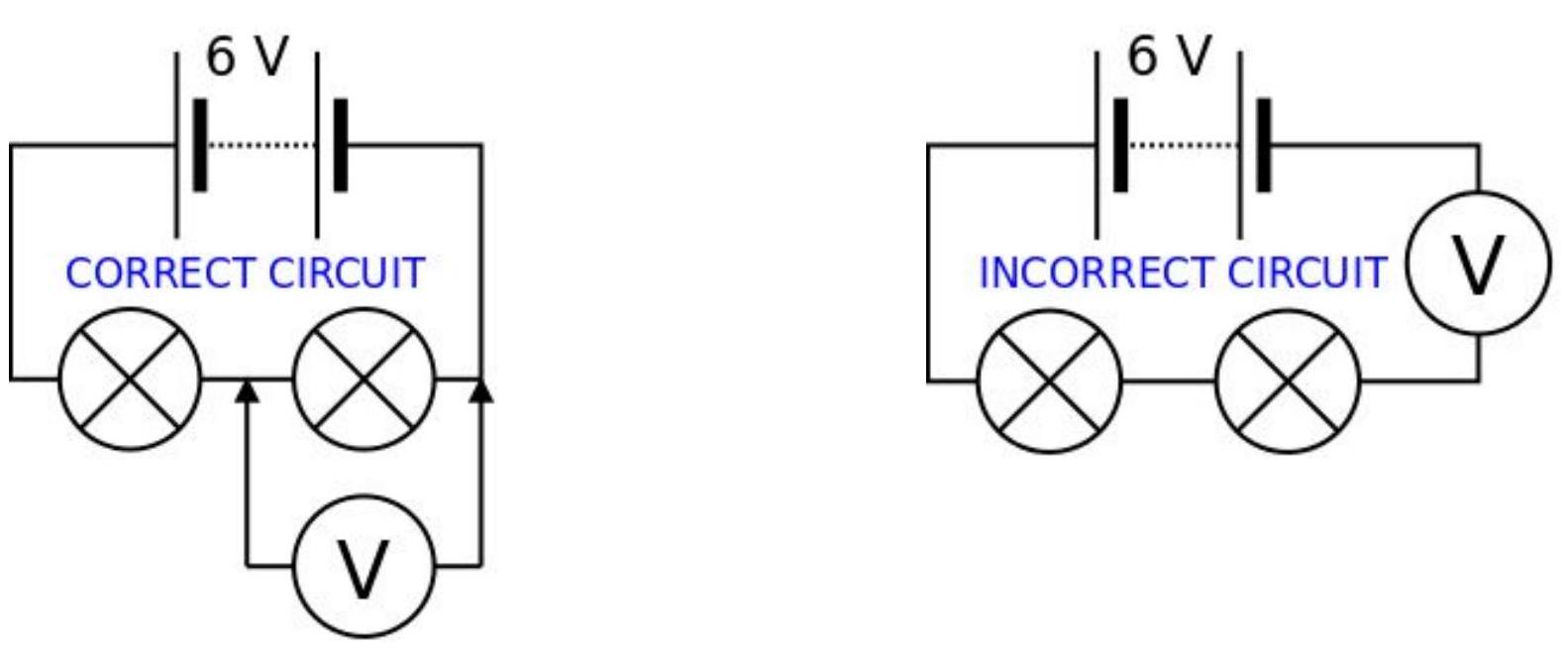
(2023-12) A student correctly builds the circuit shown with two bulbs, a battery and a voltmeter.
Both bulbs light up and the voltmeter reads 3 V .

figure

A second student uses the same components but rebuilds the circuit incorrectly with all three components in series.

For the incorrect circuit, state and explain:

  • Whether or not the bulbs are lit to full brightness
  • The approximate reading on the voltmeter
Show worked solution
(a)

In the incorrect circuit the two bulbs and the voltmeter are all connected in series with the battery, so the same current must pass through the bulbs and through the voltmeter. A voltmeter is designed to have a very large resistance (ideally infinite) so that it does not draw current when placed in parallel across a component. If it is put in series, its large resistance makes the total resistance of the circuit very large, so the current becomes extremely small: $$ I=\frac{V}{R_{\text{total}}}\approx \frac{3}{R_V+R_{b1}+R_{b2}}\approx \frac{3}{R_V}\ \ \text{since}\ \ R_V\gg R_{b1},R_{b2} $$ Because the current is tiny, the power in each bulb is tiny, so the bulbs are not lit to full brightness; they will be very dim (possibly not visibly lit).

(b)

With such a small current, the voltage drop across each bulb is very small (since $V_{\text{bulb}}=IR_{\text{bulb}}$ and $I$ is tiny), so almost the entire battery voltage appears across the voltmeter: $$ V_{\text{battery}}=V_{b1}+V_{b2}+V_V \quad \Rightarrow \quad V_V\approx V_{\text{battery}}\approx 3\ \text{V} $$ Therefore the voltmeter reading is approximately $3\ \text{V}$.

2024-14C · Writtend4Electricity and Magnetism · Battery charging circuit with internal resistance

(2024-14: Battery Charging) Batteries are an important part of modern day technology. This question is about a very simple (and unrealistic) battery charger.

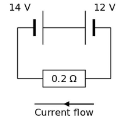
A simple charging circuit is constructed from a power supply with an EMF of 14 volts and a fixed value resistor, used to limit the current, with a resistance of $0.15\ \Omega$. The power supply and resistor are connected in series with the battery to be charged which has an EMF of 12 volts and also has an internal resistance of $0.05\ \Omega$.

figure
(a) The total resistance of the circuit due to the fixed value resistor and the internal resistance of the battery is $0.2\ \Omega$. State the potential difference across the $0.2\ \Omega$ total resistance. (b) Calculate the charging current flowing in the circuit. (c) By considering the rate of energy transfer in the power supply and the power dissipated in the $0.2\ \Omega$ total resistance, show that the efficiency of the charging process is about $85\%$.

The current flowing through the $0.05\ \Omega$ internal resistance of the battery being charged has a heating effect and therefore the temperature of the battery increases.

(d) Calculate the rate of energy transfer to the thermal (internal) energy store of the battery.

The battery manufacturer states that the temperature should not be allowed to exceed $50^{\circ}\mathrm{C}$ when the battery is being charged. The battery is a lead-acid battery made from lead electrodes immersed in sulphuric acid.

  • Mass of lead in the battery $=1.6\ \mathrm{kg}$
  • Mass of sulphuric acid in the battery $=1.0\ \mathrm{kg}$
  • Specific heat capacity of lead $=130\ \mathrm{J/(kg^{\circ}C)}$
  • Specific heat capacity of sulphuric acid $=1400\ \mathrm{J/(kg^{\circ}C)}$
  • Initial temperature of battery $=20^{\circ}\mathrm{C}$
(e) Calculate the rate of increase of temperature of the battery when it is being charged.

Assume that the battery voltage and charging current remain constant throughout the charging process. Assume that no energy is transferred to the surroundings during the charging process.

(f) Show that the battery can be charged for about $2\frac{1}{2}$ hours before it reaches the maximum allowed temperature. (g) The battery has a capacity of 50 Ah (Amp-hours). As a percentage, what fraction of the battery's capacity is transferred to the battery during the charging process before it reaches its maximum allowed temperature? (h) What would be the effect of changing the value of the fixed resistor on the percentage to which the battery is charged before it reaches its maximum allowed temperature?
Show worked solution
(a)

The potential difference across the total resistance is the difference between the supply EMF and the battery EMF: $$ V_{R}=14-12=2\ \mathrm{V} $$

(b)

Using Ohm's law: $$ I=\frac{V_{R}}{R_{\text{total}}}=\frac{2}{0.2}=10\ \mathrm{A} $$

(c)

The power supplied by the power supply is: $$ P_{\text{supply}}=VI=(14)(10)=140\ \mathrm{W} $$

The power dissipated in the $0.2\ \Omega$ resistance is: $$ P_{\text{dissipated}}=I^{2}R=(10)^{2}(0.2)=20\ \mathrm{W} $$

The power stored in the battery is: $$ P_{\text{battery}}=P_{\text{supply}}-P_{\text{dissipated}}=140-20=120\ \mathrm{W} $$

The efficiency is: $$ \eta=\frac{P_{\text{battery}}}{P_{\text{supply}}}=\frac{120}{140}\approx0.857\approx85.7\%\approx85\% $$

(d)

The rate of energy transfer to the thermal store of the battery is the power dissipated in the internal resistance ($0.05\ \Omega$): $$ P_{\text{thermal}}=I^{2}r=(10)^{2}(0.05)=5\ \mathrm{W} $$

(e)

The thermal energy is shared between the lead and the sulphuric acid. The rate of temperature increase is given by: $$ P_{\text{thermal}}=m_{\text{Pb}}c_{\text{Pb}}\frac{dT}{dt}+m_{\text{acid}}c_{\text{acid}}\frac{dT}{dt} $$ $$ 5=(1.6)(130)\frac{dT}{dt}+(1.0)(1400)\frac{dT}{dt} $$ $$ 5=208\frac{dT}{dt}+1400\frac{dT}{dt}=1608\frac{dT}{dt} $$ $$ \frac{dT}{dt}=\frac{5}{1608}\approx0.0031\ {\circ}\mathrm{C/s}=0.186\ {\circ}\mathrm{C/min}=11.2\ {\circ}\mathrm{C/hour} $$

(f)

The temperature needs to rise from $20^{\circ}\mathrm{C}$ to $50^{\circ}\mathrm{C}$, a change of $\Delta T=30^{\circ}\mathrm{C}$. At the rate calculated above: $$ t=\frac{\Delta T}{dT/dt}=\frac{30}{0.0031}\approx9680\ \mathrm{s}\approx161\ \mathrm{minutes}\approx2.7\ \mathrm{hours}\approx2\frac{1}{2}\ \mathrm{hours} $$

(g)

The charging time is about $2.7\ \mathrm{hours}$ at $10\ \mathrm{A}$, so the charge transferred is: $$ Q=It=(10)(9680)=96\,800\ \mathrm{C}=26.9\ \mathrm{Ah} $$

As a percentage of the 50 Ah capacity: $$ \frac{26.9}{50}\times100\approx54\% $$

(h)

Changing the fixed resistor would change the charging current. A larger resistor would reduce the current, which would:

  • Reduce the heating rate (slower temperature increase)
  • Allow longer charging time before reaching maximum temperature
  • Transfer a larger percentage of the battery's capacity before overheating

Conversely, a smaller resistor would increase the current, leading to faster heating and allowing a smaller percentage of capacity to be transferred before the temperature limit is reached.

2025-12B · Writtend2Electricity and Magnetism · Filament resistance and temperature

(2025-12) When current flows through a filament lamp (bulb) the filament heats up.

Explain why:

  • When the bulb is turned on and current flows, the temperature of the filament increases from its initial value to some higher temperature
  • The filament reaches a constant final temperature

Show worked solution
(a) Why the filament temperature increases after switching on

The filament has electrical resistance $R$, so when a potential difference $V$ is applied a current $I$ flows and electrical energy is transferred to the filament each second (electrical power input). This energy is mainly converted into internal (thermal) energy of the metal lattice by collisions of conduction electrons with ions (Joule heating), so the filament's temperature rises from its initial (room) value. The rate at which electrical energy is supplied is $$ P_{\text{in}}=IV=I^{2}R=\frac{V^{2}}{R} $$

Because initially the filament is relatively cool, its heat loss to the surroundings is comparatively small, so $P_{\text{in}}>P_{\text{loss}}$ and there is a net gain of thermal energy, causing temperature to increase.

(b) Why the filament reaches a constant final temperature

As the filament gets hotter, it loses energy to the surroundings more rapidly (mainly by thermal radiation and also by conduction through the support wires and convection/conduction in the gas, depending on the bulb type). The loss rate $P_{\text{loss}}$ increases strongly with temperature, so the net heating rate decreases as the filament warms. The filament reaches a steady (constant) final temperature when the rate of electrical energy input equals the rate of energy loss, so there is no further net increase in internal energy and therefore no further rise in temperature: $$ P_{\text{in}}=P_{\text{loss}} $$

At this equilibrium temperature, the filament may still be receiving and losing energy continuously, but the two rates are equal, so the temperature remains constant.